Introducing 1:1 NAT on AWS Transit Gateway and AWS Cloud WAN
Overlapping IP addresses keep networks from connecting, and you can now resolve them with one-to-one network address translation (1:1 NAT) on AWS Transit Gateway and AWS Cloud WAN. Overlaps often follow a merger or acquisition, an integration with a third-party partner, or multicloud connectivity with other cloud service providers (CSPs). You find them inside your own Amazon Virtual Private Cloud (Amazon VPC) networks or in routes advertised from on-premises and partner networks. When two networks use the same prefix, a route table can send that prefix to only one of them.
With 1:1 NAT, each network gets a unique range through native integration with Regional Private NAT Gateway. You don’t renumber networks or deploy a separate NAT solution.
In this post, we cover three scenarios that show how 1:1 NAT works with AWS Transit Gateway and AWS Cloud WAN. In the first scenario, we implement NAT rules on VPC attachments that have overlapping IP addresses and connect through a transit gateway. In the second scenario, we implement 1:1 NAT on an AWS Direct Connect gateway (DXGW) attachment used for multicloud connectivity. In the third scenario, we implement the feature on AWS Site-to-Site VPN attachments of AWS Cloud WAN when multiple external networks advertise overlapping Classless Inter-Domain Routing (CIDR) ranges.
How it works
With AWS Transit Gateway and AWS Cloud WAN, you can configure static, stateless 1:1 NAT at the attachment level through Regional Private NAT Gateway integration. The host portion of each address stays the same. For example, if 10.10.100.0/24 maps to 100.64.100.0/24, then 10.10.100.5 becomes 100.64.100.5. Ports never change, so this differs from port address translation. You define NAT rules per attachment, and each rule maps a Match source CIDR to a translated NAT CIDR. These rules follow a few constraints:
- The NAT CIDR comes from RFC 1918 (10.0.0.0/8, 172.16.0.0/12, 192.168.0.0/16) or RFC 6598 (100.64.0.0/10).
- The NAT CIDR carries the same netmask length as the original Match source CIDR.
- Each CIDR needs its own rule with its own rule number. Attachments with multiple CIDRs need multiple NAT rules.
- Translation applies automatically in both directions, so you do not write separate return-traffic rules.
After you turn on NAT, other networks reach a translated attachment through its NAT CIDR. A route to that NAT CIDR must exist in the route table. The NAT system routes setting determines who creates that route. When the setting is on, AWS Transit Gateway or AWS Cloud WAN creates a route of a new type, system, and points it to the attachment. When it’s off, the network behind the attachment advertises the NAT CIDR over Border Gateway Protocol (BGP), and the service learns it as a propagated route.
1:1 NAT translates IP addresses only. It doesn’t rewrite DNS responses, so a host name still resolves to its original pre-NAT address. Before you turn on NAT, update each DNS record to its post-NAT address. Clients that still resolve a host name to the original address lose connectivity.
Scenario 1: Implementing 1:1 NAT on overlapping VPC CIDRs
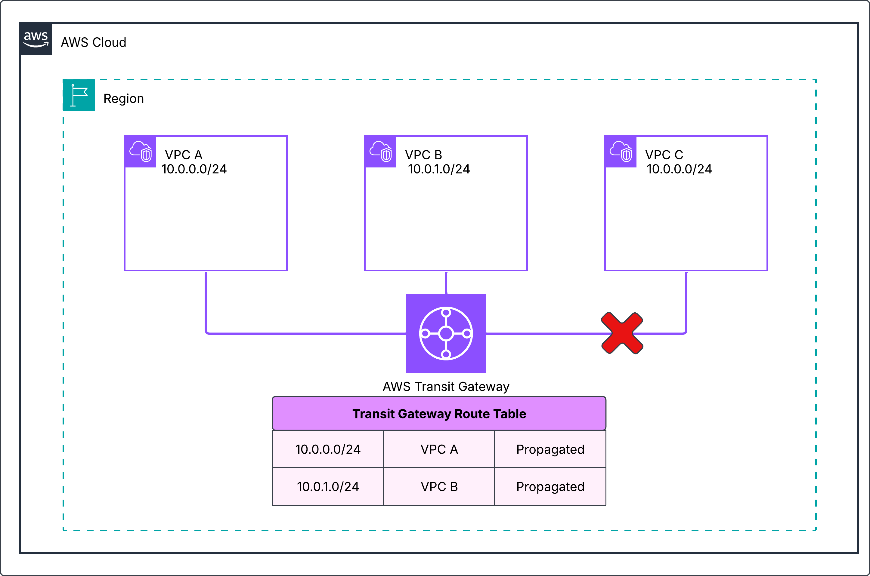
You run a hub-and-spoke network on AWS Transit Gateway, and an acquisition brings an overlapping IP range. As shown in the following figure, VPC A (10.0.0.0/24) and VPC B (10.0.1.0/24) attach to a transit gateway and communicate without issue. VPC C (10.0.0.0/24) from the acquisition is identical to the VPC A range, so the transit gateway route table installs only one route for 10.0.0.0/24 and connectivity cannot be established.
Figure 1: No connectivity between VPCs because of overlapping CIDRs
You resolve the overlap by configuring NAT rules on both overlapping attachments. First, select Enable NAT Gateway support on each attachment. As shown in the following figure, you then create a NAT rule on the VPC A attachment that maps 10.0.0.0/24 to 100.64.0.0/24. On the VPC C attachment, you map 10.0.0.0/24 to 100.64.1.0/24. VPC B doesn’t overlap, so it needs no NAT. On VPC attachments, the NAT system routes setting stays on and you can’t turn it off.
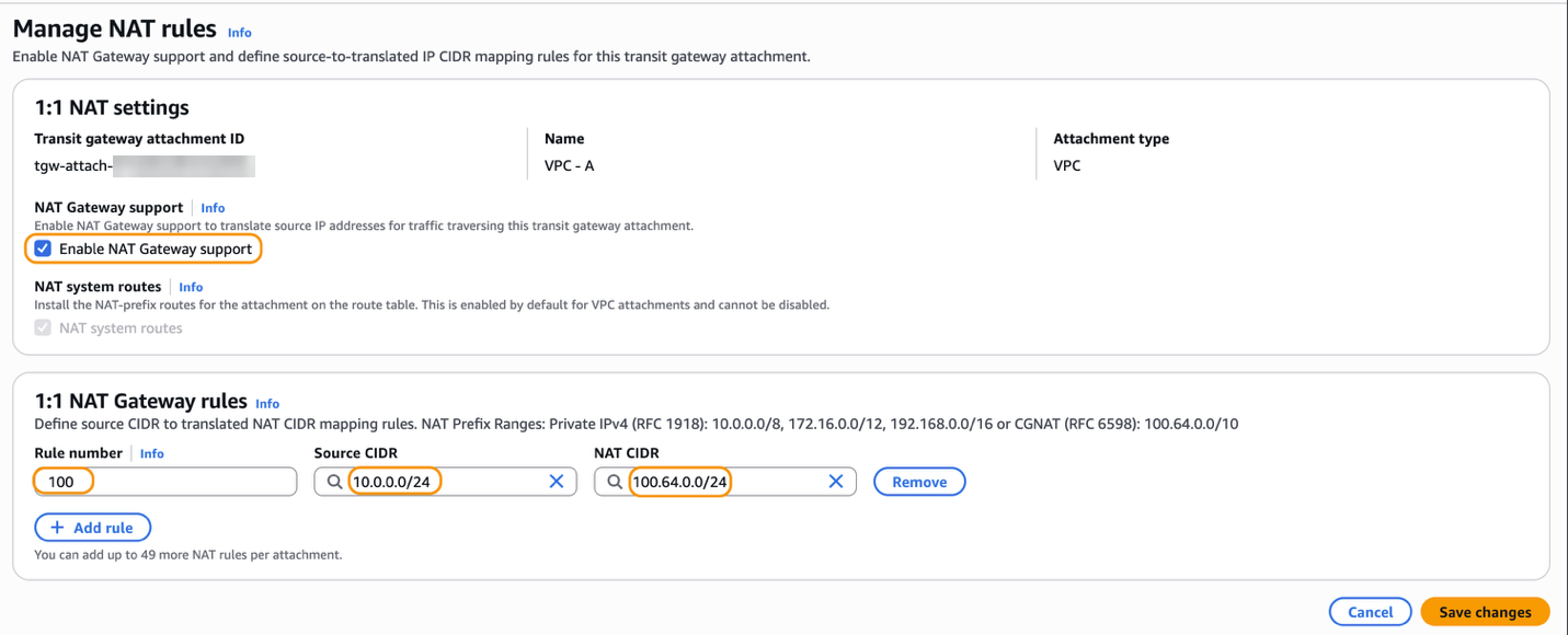
Figure 2: Create NAT rules on the transit gateway attachment
In this scenario, both overlapping attachments need NAT rules because the ranges are identical. If you turn on NAT for only one VPC, the other VPC replies to an address inside its own range. Its route table then delivers that traffic locally instead of sending it to the transit gateway, so the connection fails.
The following figure shows the transit gateway route table with a system route for each NAT CIDR, 100.64.0.0/24 and 100.64.1.0/24. VPC B’s 10.0.1.0/24 stays a propagated route because it has no NAT.

Figure 3: Transit gateway route table with system routes for the translated prefixes
If an application in VPC B resolves db.example.com to 10.0.0.25, that address stops working because the system route for 100.64.0.0/24 replaces the propagated route for 10.0.0.0/24. Update the DNS record to 100.64.0.25 first and add a route for 100.64.0.0/24 to the transit gateway in the VPC B route table.
Packet walkthrough
The following steps trace a packet from 10.0.0.5 in VPC A to 10.0.0.18 in VPC C and back, as shown in the following figure.
- The Amazon Elastic Compute Cloud (Amazon EC2) instance in VPC A sends traffic to the instance in VPC C at its translated address 100.64.1.18.
- NAT rules on the VPC A attachment translate the source 10.0.0.5 to 100.64.0.5.
- The transit gateway routes the packet to the VPC C attachment by using the 100.64.1.0/24 system route.
- NAT rules on the VPC C attachment rewrite destination 100.64.1.18 to 10.0.0.18.
- For return traffic, NAT rules on the VPC C attachment rewrite source 10.0.0.18 to 100.64.1.18.
- The transit gateway routes the traffic to the VPC A attachment by using the 100.64.0.0/24 system route.
- NAT rules on the VPC A attachment rewrite destination 100.64.0.5 to 10.0.0.5.
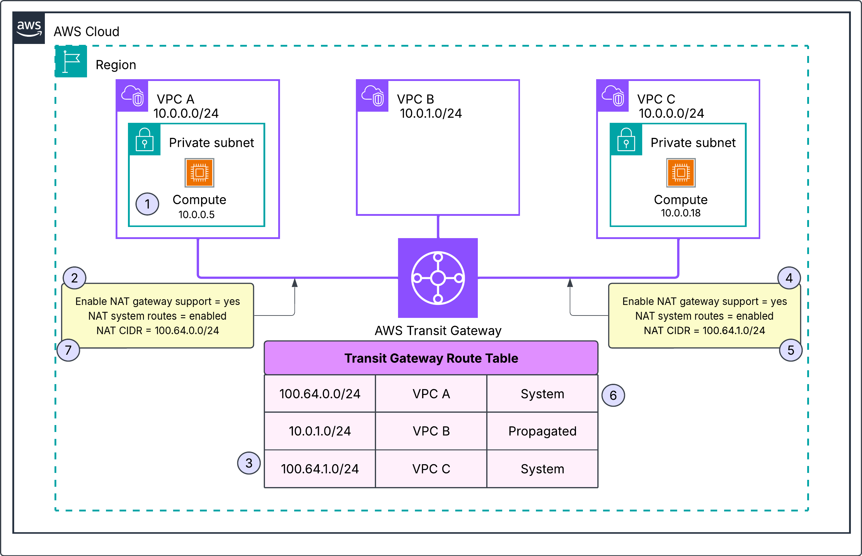
Figure 4: Packet walkthrough with 1:1 NAT on both VPC attachments
Scenario 2: Implementing 1:1 NAT on AWS Interconnect – multicloud connection
You run workloads across AWS and another CSP, and their IP ranges overlap. As shown in the following figure, you connect the two through AWS Interconnect – multicloud. The connection terminates on a DXGW attachment on your transit gateway, as explained in the AWS Interconnect multicloud post. The CSP network advertises 172.16.0.0/24, which overlaps with VPC A (172.16.0.0/24), so the two environments can’t connect. VPC B (10.0.1.0/24) also attaches to the transit gateway and needs no NAT.
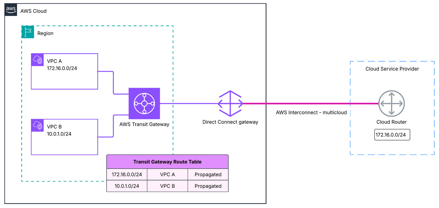
Figure 5: Overlapping IP addresses between workloads hosted across cloud providers
To resolve this overlap, select Enable NAT Gateway support on both attachments with overlapping CIDRs. On the VPC A attachment, you translate 172.16.0.0/24 to 100.64.2.0/24. On the DXGW attachment where the AWS Interconnect – multicloud connection terminates, you translate the CSP range 172.16.0.0/24 to 100.64.3.0/24, as shown in the following figure.
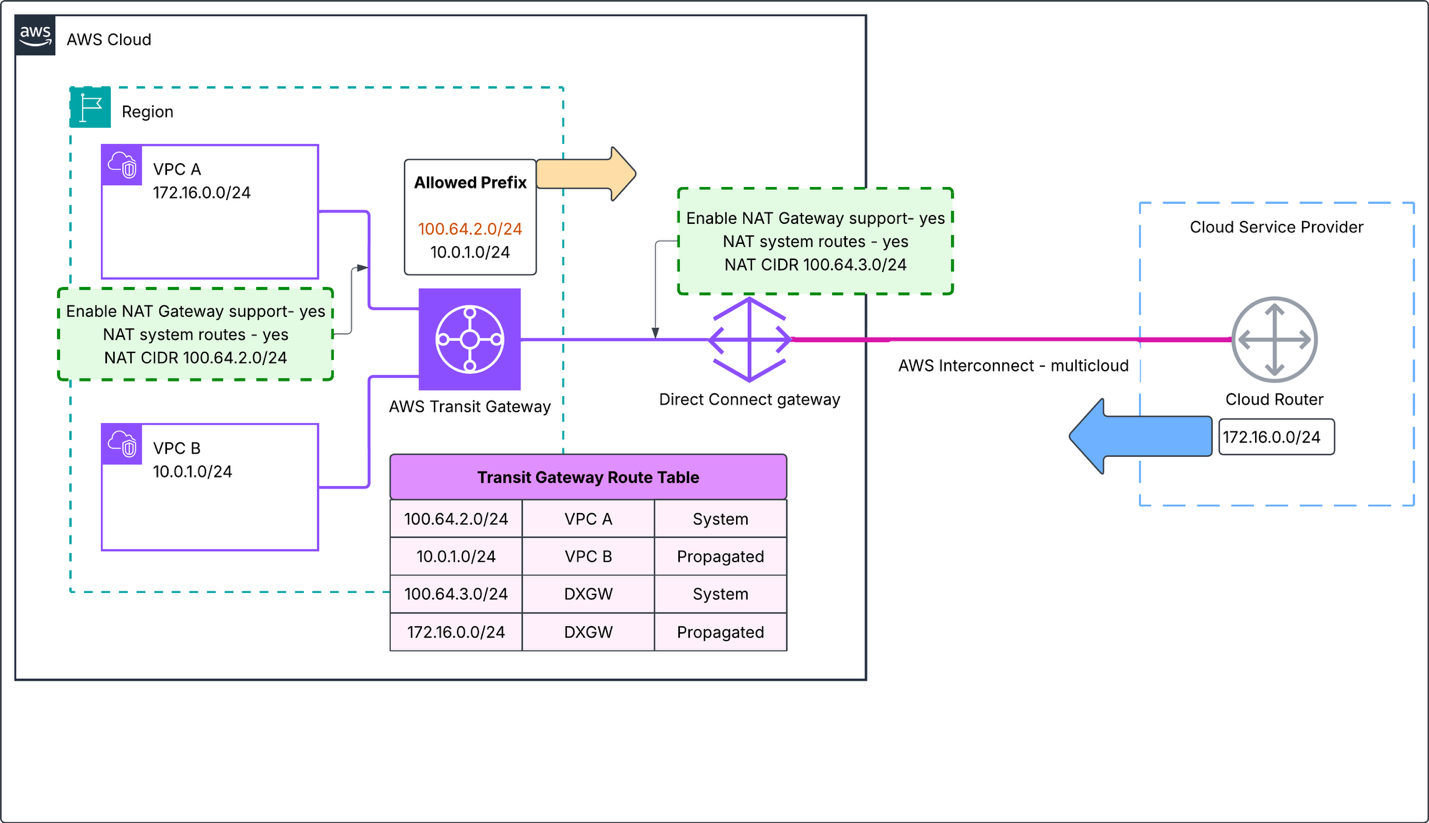
Figure 6: 1:1 NAT on the DXGW and VPC A attachments
You keep NAT system routes turned on for the DXGW attachment. The transit gateway then installs a system route for 100.64.3.0/24 that points to the DXGW attachment. The following figure shows the route table, which also lists 100.64.2.0/24 as a system route to VPC A and 10.0.1.0/24 as a propagated route to VPC B. If you turn the setting off, the CSP router must advertise 100.64.3.0/24 over BGP.

Figure 7: Transit gateway route table with NAT system routes turned on for the DXGW attachment
With the NAT system routes setting turned on, the CSP’s original 172.16.0.0/24 route stays propagated. Traffic from another transit gateway attachment that still targets the original VPC A addresses goes to the CSP. Update the DNS records to the correct post-NAT IP addresses before you turn on 1:1 NAT on the respective attachments.
Scenario 3: Identifying overlapping partner networks over AWS Site-to-Site VPN
You connect two third-party partner networks to your AWS Cloud WAN core network. As shown in the following figure, the Workload Segment holds VPC A (10.0.0.0/24) and VPC B (10.10.0.0/24) in two different Regions. The External Segment has isolation turned on and holds two AWS Site-to-Site VPN attachments, one for each partner. Both partners advertise 192.168.0.0/26, so AWS Cloud WAN cannot tell them apart and connectivity cannot be established.
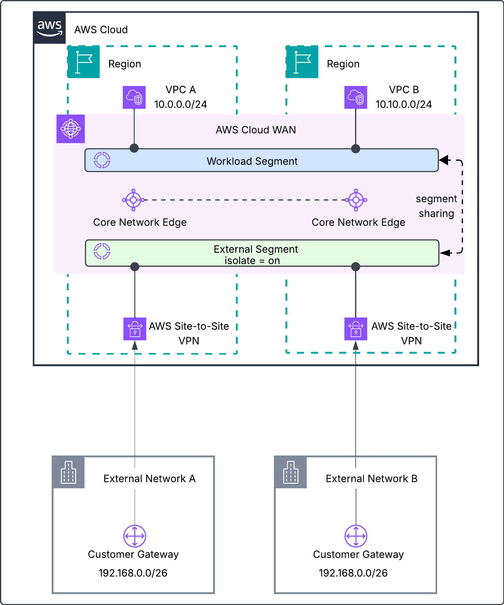
Figure 8: Two partner Site-to-Site VPN attachments on AWS Cloud WAN both advertise 192.168.0.0/26
The following figure shows the core network Routing Information Base (RIB) in one Region. Both partners advertise 192.168.0.0/26 over both VPN tunnels with AS path and multi-exit discriminator (MED) attributes, and AWS Cloud WAN installs it as a propagated route.
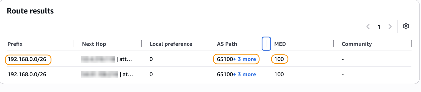
Figure 9: Partner networks advertising an overlapping CIDR with BGP attributes set
Turn on NAT gateway support on both VPN attachments. The first partner’s 192.168.0.0/26 translates to 100.64.0.0/26, as shown in the following figure, and the second partner’s 192.168.0.0/26 translates to 100.64.64.0/26.
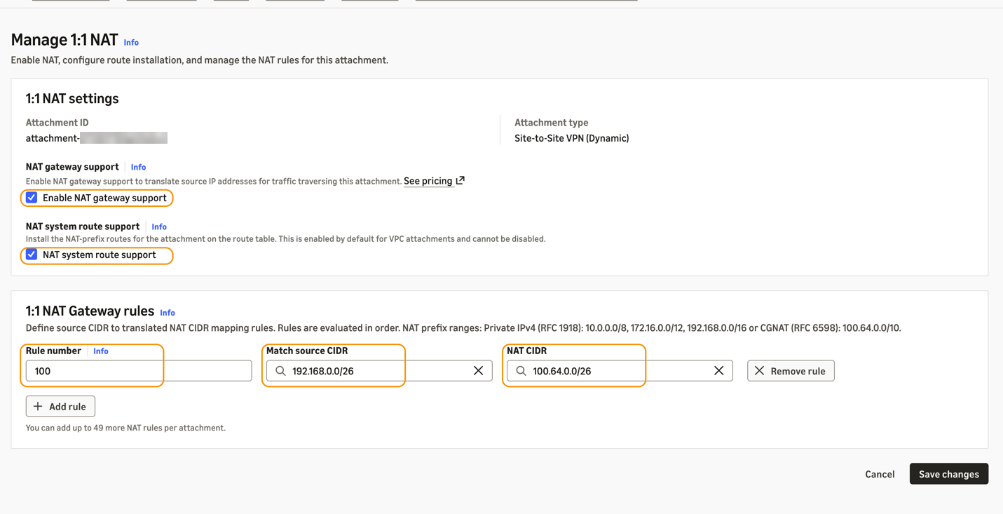
Figure 10: Turning on 1:1 NAT on a dynamic Site-to-Site VPN attachment
Each partner now appears in the Workload Segment as a unique range. A partner host 192.168.0.25 appears as 100.64.0.25 from the first partner and 100.64.64.25 from the second.
You keep NAT system route support turned on for both VPN attachments. AWS Cloud WAN then originates a system route for 100.64.0.0/26 toward the first attachment and 100.64.64.0/26 toward the second, while 192.168.0.0/26 stays propagated. The following figure shows 100.64.0.0/26 in the core network RIB without the original BGP attributes, such as the AS path and MED.
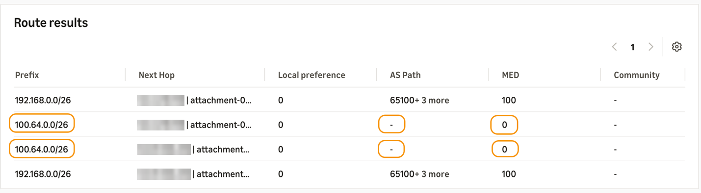
Figure 11: NAT CIDR without BGP attributes when NAT system route support is on
If a partner uses both VPN tunnels for equal-cost multipath (ECMP) routing or a primary and standby design, we recommend that you turn off NAT system route support on that partner’s VPN attachment. In that case, the partner’s BGP speaker must advertise its NAT CIDR. The partner should also stop advertising the overlapping 192.168.0.0/26, so the two routes do not compete in the route table. AWS Cloud WAN then learns each NAT CIDR as a propagated route with its full BGP attributes, as shown in the following figure.
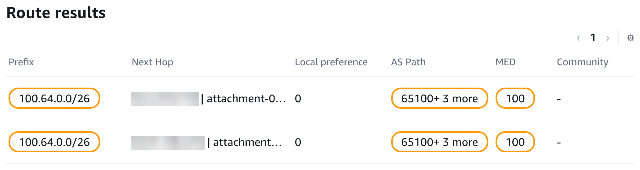
Figure 12: NAT CIDR with BGP attributes when NAT system route support is off
Because segment sharing connects the External Segment to the Workload Segment, the workload VPCs can reach each partner. Traffic to a translated prefix routes to the matching VPN attachment, where the core network edge (CNE) rewrites the destination back to 192.168.0.0/26, as the following figure shows.
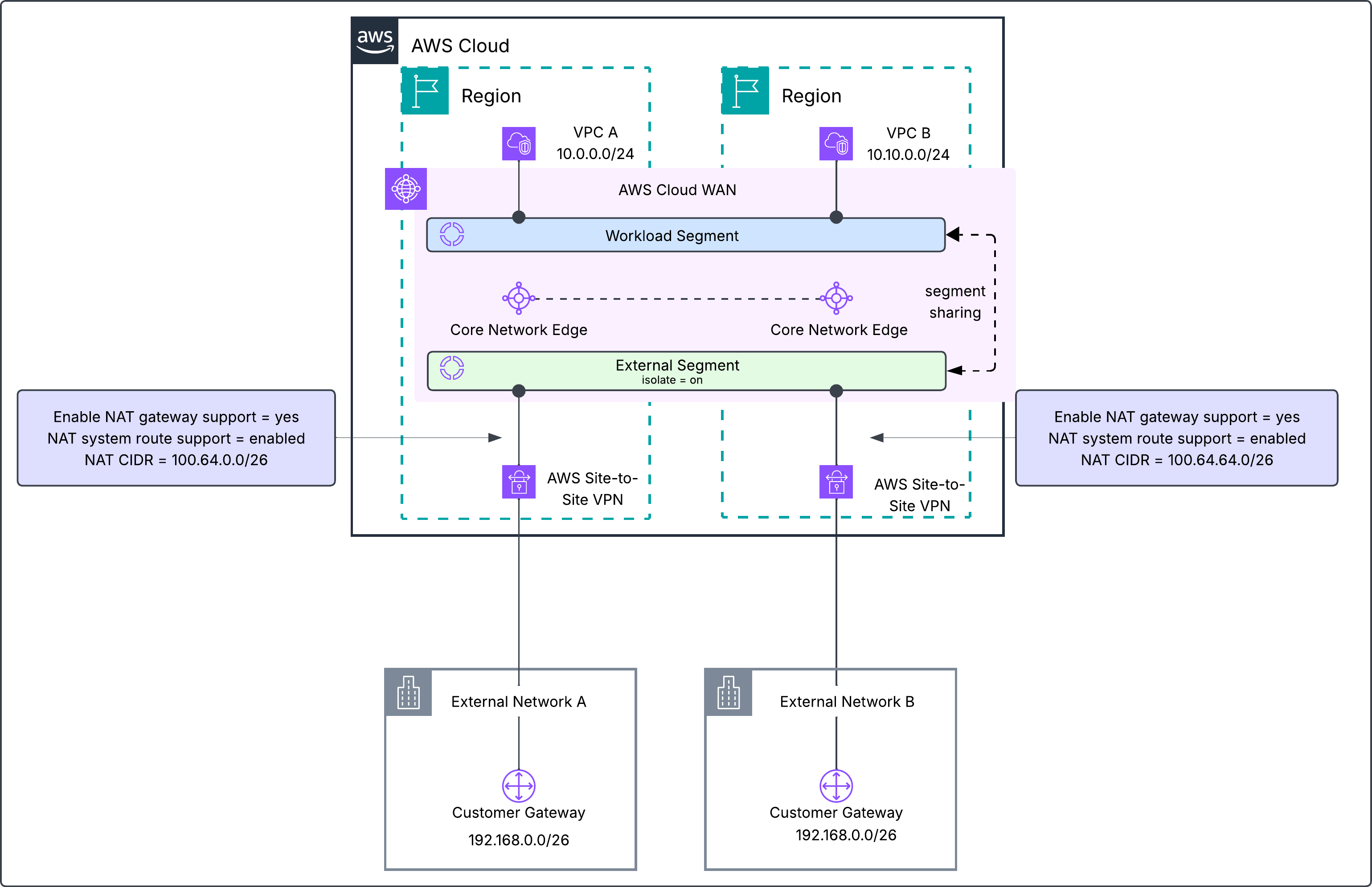
Figure 13: 1:1 NAT on AWS Site-to-Site VPN attachments on AWS Cloud WAN
Considerations
Keep these points in mind when you plan 1:1 NAT.
- IPv4 only – 1:1 NAT supports IPv4 address translation only.
- Supported attachment types – See AWS Transit Gateway supported attachment types and AWS Cloud WAN supported attachment types.
- Match source CIDR ranges – Unlike the NAT CIDR, the Match source CIDR isn’t limited to RFC 1918 or RFC 6598 ranges. It can’t overlap multicast (224.0.0.0/4) or link-local (169.254.0.0/16) ranges.
- System route precedence – A system route ranks below a static route and above a propagated route.
- NAT system routes – With the setting turned on, a system route depends on the original route that your network advertises. If your network stops advertising a route that overlaps the Match source CIDR, the system route moves to a blackhole state and traffic to the NAT CIDR drops. When the service advertises a NAT CIDR to other BGP-capable attachments, the AS path shows the transit gateway or AWS Cloud WAN core network edge autonomous system number (ASN) as the originator. Your network’s original AS path and MED don’t carry over.
- Connect and transport attachment mutual exclusivity – NAT on a Connect attachment and NAT on its transport attachment are mutually exclusive. A transport attachment hosting a tunnelless Connect (TLC) attachment doesn’t support 1:1 NAT.
- Appliance mode – You can’t turn on NAT on a VPC attachment that has appliance mode turned on.
Conclusion
In this post, we showed how you can use Regional Private NAT Gateway integration to add managed 1:1 NAT to AWS Transit Gateway and AWS Cloud WAN. You translated both overlapping VPC attachments after an acquisition, the VPC A and DXGW attachments for multicloud connectivity, and two partner VPN attachments on AWS Cloud WAN. In every case, the translated NAT CIDR uses the same netmask length as the Match source CIDR and comes from RFC 1918 or RFC 6598 address space. With this integration, you get predictable, managed address translation without building and operating your own NAT solutions.
1:1 NAT is available in all AWS commercial Regions where AWS Transit Gateway and AWS Cloud WAN operate. For pricing, see Amazon VPC pricing. To get started, see the AWS Transit Gateway 1:1 NAT documentation and the AWS Cloud WAN 1:1 NAT documentation. If you have questions or feedback, share them on AWS re:Post or reach out through AWS Support.